Tang Nano 4K に搭載されているFPGA GW1NSR-LV4CQN48P に内蔵のMPU(empu)から回路を制御するのに、APBを利用しようと考えています。APBの仕様書はAMBA® APB Protocol Specification で、ARMから入手可能です。
今回は、APBの触り?を試してみました。
予め断っておきますが、この記事の内容は私の備忘録で適当です(笑)
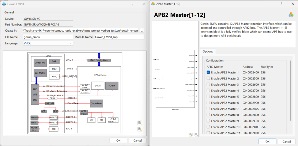
まずは、empuのブロック図のAPB2 Master[1-12]をクリックし、APB2 Masterで Enable APB2 Master 1 をチェックします。
これで、Base Address 0x40002400から256Byte分がアクセスできるようになります。

生成された、EMPUのComponent定義等をコピーします。
次は、APB Completerをつくります。
自分で一から書こうかなと思いましたが、BingのCopilotにお願いしてみました(笑)
とりあえず試すことはできそうなコードを生成してくれました。
これにちょっと手を加えて、READ,WRITEのテスト機能を追加しました。
|
1 2 3 4 5 6 7 8 9 10 11 12 13 14 15 16 17 18 19 20 21 22 23 24 25 26 27 28 29 30 31 32 33 34 35 36 37 38 39 40 41 42 43 44 45 46 47 48 49 50 51 52 53 54 55 56 57 58 |
-- -- APB BUS TEST -- library IEEE; use IEEE.std_logic_1164.all; use IEEE.std_logic_unsigned.all; entity APB_IO is port( pclk: in std_logic; -- Clock prst: in std_logic; -- Reset penable: in std_logic; -- Enable paddr: in std_logic_vector(7 downto 0); -- Adress pwrite: in std_logic; -- direction, read/write pwdata: in std_logic_vector(31 downto 0); -- Write data -- pstrb: in std_logic_vector(3 downto 0); -- Write strobe -- not use -- pprot: in std_logic_vector(2 downto 0); -- Protection type -- not use psel: in std_logic; -- Select prdata: out std_logic_vector(31 downto 0); -- Read data pready: out std_logic; -- Ready pslverr: out std_logic; -- slave transfer failure outport: out std_logic; -- output for test inport : in std_logic -- input for test ); end entity; architecture RTL of APB_IO is begin process(pclk, prst) begin if prst = '0' then prdata <= (others => '0'); pready <= '0'; pslverr <= '0'; elsif rising_edge(pclk) then if psel = '1' and penable = '1' then pready <= '1'; -- should hold '0' until data or operation valid if pwrite = '1' then -- Write register case paddr is when x"00" => outport <= pwdata(0); when others => outport <= '0'; end case; else -- Read register case paddr is when x"00" => prdata <= x"41424344"; --ABCD when x"04" => prdata <= x"45464748"; --EFGH when x"08" => prdata <= x"494A4B4C"; --IJKL when others => prdata <= x"58585858"; --XXXX end case; end if; else pready <= '0'; end if; end if; end process; end RTL; |
Base Address の1ビット目に書き込むとポートがH/Lします。
Base Address からオフセット 0, 4, 8で読みだすと、ABCD, EFGH, IJKLを返します。
empu側からAPB経由でREAD,WRITEするサンプルコードです。
|
1 2 3 4 5 6 7 8 9 10 11 12 13 14 15 16 17 18 19 20 21 22 23 24 25 26 27 28 29 30 31 32 33 34 35 36 37 38 39 40 41 42 43 44 45 46 47 48 49 50 51 52 53 54 55 56 |
#define APB_TIC0_BASE 0x40002400 void writeAPB_TIC0(uint32_t data) { APB_TIC0->outReg0 = data; } uint32_t readAPB_TIC0(uint32_t offset) { return *(uint32_t*)(APB_TIC0_BASE + offset); } typedef union dw2b{ uint32_t dword; uint8_t byte[4]; }dw2b_t; uint8_t* chgOrder(uint8_t* str, uint32_t src) { str[0] = ((dw2b_t)src).byte[3]; str[1] = ((dw2b_t)src).byte[2]; str[2] = ((dw2b_t)src).byte[1]; str[3] = ((dw2b_t)src).byte[0]; str[4] = 0x00; return str; } //Task 2 static void led1_task(void *pvParameters) { uint8_t str[5] = {0}; uint32_t c, d; uint8_t n = 0; while (1){ if (0 == led1_task_flag){ GPIO_ResetBit(GPIO0, GPIO_Pin_1); led1_task_flag = 1; writeAPB_TIC0((uint32_t)0x00); tiny_printf("LED1 TASK Offset %3d: %x", c = (n %4)*0x04, d = readAPB_TIC0(c)); n++; tiny_printf(", char %s\r\n",chgOrder(str, d)); } else{ GPIO_SetBit(GPIO0, GPIO_Pin_1); led1_task_flag = 0; writeAPB_TIC0((uint32_t)0x01); } vTaskDelay(TASK_DELAY_MS_TO_TICK(500)); } } |
empuはバイトオーダーがリトルエンディアンなので、バイトの入れ替えをしています。
サンプルコードに使われているprintf_str関数は、printfとついているにも関わらず、単にUARTにデータを流すだけで使い勝手が悪いので、tiny_printfを入れました。
UART0からの出力です。

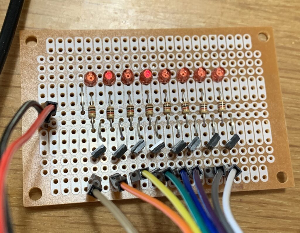
出力モニターです(笑)
年末に大掃除もそこそに作りました。
実際に使うには、レジスタとの接続などまだまだ処理が必要ですが、とりあえずここまで。
